Would you like to learn how to configure Cisco Vlan routing using the command-line? In this tutorial, we are going to show you all the steps required to configure Ip routing between virtual interfaces on a Cisco Switch 3750 using the command-line.
You need to verify if your Switch IOS support multiple virtual interfaces.
Usually switches like 2960 support only 1 virtual interface.
You need a switch that supports the minimum of 2 virtual interfaces.
Cisco Switch Playlist:
On this page, we offer quick access to a list of videos related to Cisco Switch.
Don't forget to subscribe to our youtube channel named FKIT.
Cisco Switch Related Tutorial:
On this page, we offer quick access to a list of tutorials related to Cisco Switch.
Tutorial - Vlan Routing on Cisco Switch
First, you need to access the console of your Cisco Switch.
In our example, we are going to use an Opensource software named Putty and a computer running Windows.
The Putty software is available on the putty.org website.
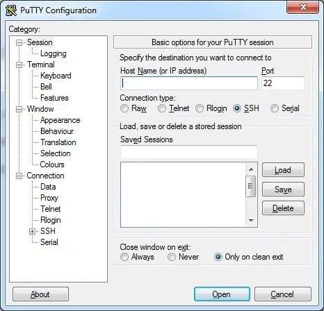
After finishing the download, run the software and wait for the following screen.

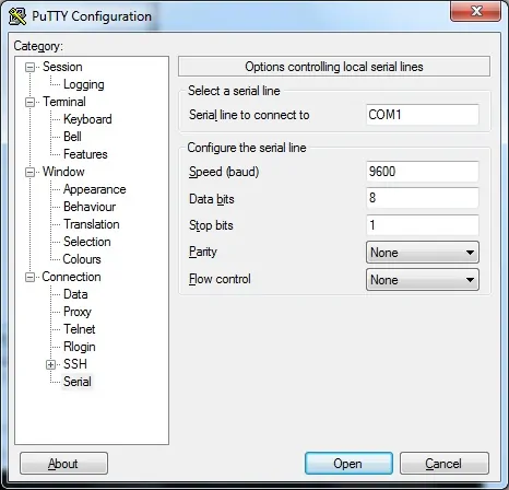
To access the console of a Cisco Switch model 2960 or 3750, you will need to select the Serial Connection category and use the following options:
• Connection type: Serial
• Serial line: COM1
• Speed: 9600
If COM1 does not work you will need to try to use COM2, COM3, COM4 or the next.

Using either the console, telnet or ssh, connect to the command-line of your switch and log in with a user who has administrative privileges.
On the prompt screen, enter the administrative login information.
After a successful login, the console command-line will be displayed.
Switch>
Use the enable command to enter the privilege mode.
Switch> enable
Use the configure terminal command to enter the configuration mode.
Switch# configure terminal
Create 2 new Vlans, select an identification number and add a brief description.
Switch(config)# vlan 100
Switch(config-vlan)# name Server Network
Switch(config)# vlan 200
Switch(config-vlan)# name Desktop Network
Switch(config-vlan)# exit
On the configuration mode, you need to create 2 virtual interfaces.
Switch(config)# interface vlan 100
Switch(config-if)# ip address 192.168.100.1 255.255.255.0
Switch(config-if)# exit
Switch(config)# interface vlan 200
Switch(config-if)# ip address 192.168.200.1 255.255.255.0
Switch(config-if)# exit
On the configuration mode, you need to enable IP routing on the device.
Switch(config)# ip routing
Switch(config)# exit
In our example, the virtual switch interfaces Vlan100 and Vlan200 were configured.
In our example, the IP routing feature was enabled on the device.
To test your configuration, configure a switch port on the Desktop Vlan.
Switch(config)# interface gigabitethernet0/40
Switch(config)# switchport mode access
Switch(config-if)# switchport access vlan 200
Switch(config-if)# exit
Switch(config)# exit
Connect a computer on the switch port 40, configure an IP address on the same network.
Use the Switch's virtual interface IP as the default gateway.
IP address: 192.168.200.10
Netmask: 255.255.255.0
Gateway: 192.168.200.1
Open a DOS prompt and try to ping to the IP address of the virtual interface 100.
C:\> ping 192.168.100.1
In our example, the Vlan routing feature was configured on a Cisco Switch.
Don't forget to save your switch configuration.
Switch# copy running-config startup-config
You have successfully configured routing between Vlans on a Cisco switch.
