Would you like to learn how to configure GLBP on Cisco Switch using the command-line? In this tutorial, we are going to show you all the steps required to configure GLBP on a Cisco Switch using the command-line.
• Catalyst 3750
Cisco Switch Playlist:
On this page, we offer quick access to a list of videos related to Cisco Switch.
Don't forget to subscribe to our youtube channel named FKIT.
Cisco Switch Related Tutorial:
On this page, we offer quick access to a list of tutorials related to Cisco Switch.
Tutorial - GLBP Configuration on Cisco Switch
First, you need to access the console of your Cisco Switch.
In our example, we are going to use an Opensource software named Putty and a computer running Windows.
The Putty software is available on the putty.org website.
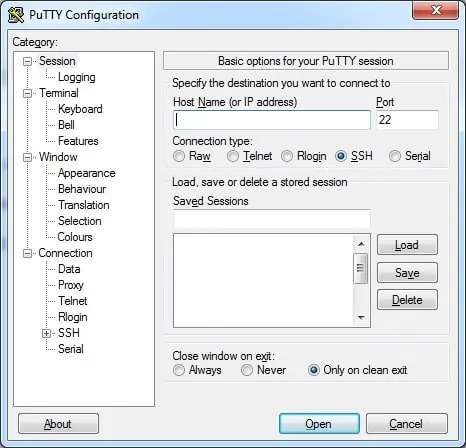
After finishing the download, run the software and wait for the following screen.

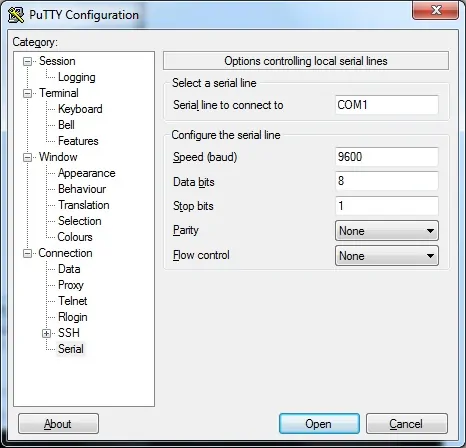
To access the console of a Cisco Switch model 2960 or 3750, you will need to select the Serial Connection category and use the following options:
• Connection type: Serial
• Serial line: COM1
• Speed: 9600
If COM1 does not work you will need to try to use COM2, COM3, COM4 or the next.

Using either the console, telnet or ssh, connect to the command-line of your switch and log in with a user who has administrative privileges.
On the prompt screen, enter the administrative login information.
After a successful login, the console command-line will be displayed.
Use the enable command to enter the privilege mode.
Use the configure terminal command to enter the configuration mode.
In our example, all company desktop are located on the VLAN 100.
All computers located on the VLAN 100 will belong to the network 192.168.100.0/24
On Switch A:
Create a new vlan, select an identification number and add a brief description.
Now, you need to perform the following configuration:
• Create a new Vlan interface - Vlan100
• Set a Vlan interface IP address - 192.168.100.2/24
• Set a Vlan interface Description - Desktop network interface
• Set an GLBP IP address - 192.168.100.1
• Set an GLBP higher priotiry - Priority 105 will make this Switch the preferred GLBP master
• Enable the GLBP preempt feature - This Switch will always try to be the GLBP master
• Configure an GLBP password for protection - MYGLBPASS
There must be a Vlan communication between SwitchA and SwitchB.
Configure a Switch port as a Trunk and connect SwitchA to SwitchB.
As a test, access the interface configuration mode and associate a switch port to the desired Vlan.
In our example, we configured the Switch port 10 as a member of Vlan 100.
Don't forget to save your configuration.
Connect a desktop to the Switch port 10 and try to ping to the following IP addresses:
• Ping to the Switch A IP address - 192.168.100.2
• Ping to the Switch B IP address - 192.168.100.3
• Ping to the GLBP IP address - 192.168.100.1
On Switch B:
Create a new vlan, select an identification number and add a brief description.
Now, you need to perform the following configuration:
• Create a new Vlan interface - Vlan100
• Set a Vlan interface IP address - 192.168.100.3/24
• Set a Vlan interface Description - Desktop network interface
• Set an GLBP IP address - 192.168.100.1
• Enable the GLBP preempt feature - This Switch will always try to be the GLBP master
• Configure an GLBP password for protection - MYGLBPPASS
There must be a Vlan communication between SwitchA and SwitchB.
Configure a Switch port as a Trunk and connect SwitchA to SwitchB.
As a test, access the interface configuration mode and associate a switch port to the desired Vlan.
In our example, we configured the Switch port 10 as a member of Vlan 100.
Don't forget to save your configuration.
Connect a desktop to the Switch port 10 and try to ping to the following IP addresses:
• Ping to the Switch A IP address - 192.168.100.2
• Ping to the Switch B IP address - 192.168.100.3
• Ping to the GLBP IP address - 192.168.100.1
You have successfully configured GLBP on a Cisco Switch.
