Would you like to learn how to perform the HP Switch Intervlan routing configuration using the command-line instead of using the web interface? In this tutorial, we are going to show you all the steps required to configure the VLAN routing feature using an HP Switch 5500 using the command-line.
Copyright © 2018-2021 by Techexpert.tips.
All rights reserved. No part of this publication may be reproduced, distributed, or transmitted in any form or by any means without the prior written permission of the publisher.
Equipment list
Here you can find the list of equipment used to create this tutorial.
This link will also show the software list used to create this tutorial.
HP Switch Book
Despite having a good knowledge related to computer networks and even have some certifications on the subject, Luke, a 26-year-old IT analyst has just received a mission to deploy a new network using only HP switches.
Follow Luke’s history and a step by step approach to a network project implementation created by a certified project management professional.
HP Switch Playlist:
On this page, we offer quick access to a list of videos related to HP Switch.
Don't forget to subscribe to our youtube channel named FKIT.
HP Switch Related Tutorial:
On this page, we offer quick access to a list of tutorials related to HP Switch.
Tutorial HP Switch - InterVlan routing
First, you need to access the console of your HP Switch.
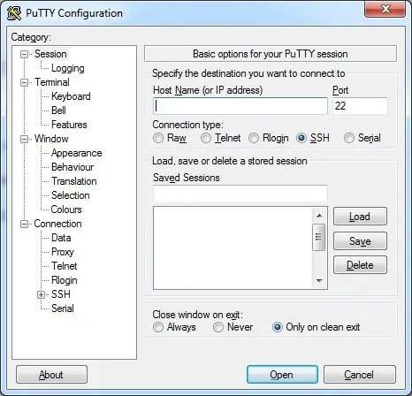
In our example, we are going to use a Opensource software named Putty and a computer running Windows.
The Putty software is available on the putty.org website.
After finishing the download, run the software and wait for the following screen.

To access the console of an HP Switch model 5500, you will need to select the Serial Connection category and use the following options:
• Connection type: Serial
• Serial line: COM1
• Speed: 9600
If COM1 does not work you will need to try to use COM2, COM3, COM4 or the next.

On the prompt screen, enter the administrative login information.
Factory default access information:
• Username: admin
• Password: (No password)
After a successful login, the console command-line will be displayed.
Use the system-view command to enter the configuration mode.
Create the required VLANS, select an identification number and add a brief description.
Create the required virtual interfaces using the following commands.
Every computer on the 192.168.100.0/24 network should point to 192.168.100.1 as the default gateway.
Every computer on the 192.168.200.0/24 network should point to 192.168.200.1 as the default gateway.
The Layer 3 switch will be responsible for routing the packets between 192.168.100.0/24 and the 192.168.200.0/24 networks.
If you need to create a default route, use the following command as an example:
Don't forget to save your switch configuration.
Congratulations! You have successfully configured the Inter VLAN routing feature.

