Would you like to learn how to configure the OPNsense Vlan feature? In this tutorial, we are going to show you how to perform a Vlan configuration on a OPNsense server.
• OPNsense 19.7
Here is a list of the existent interfaces on our OPNsense server before our configuration:
• WAN - 200.200.200.200
• LAN - 192.168.1.1
In our example, we are going to create a VLAN sub-interface named OPT1 on the LAN Physical interface.
The sub-interface named OPT1 will be a member of the VLAN 10 and will use the IP address 192.168.10.1:
Here is a list of the interfaces on our OPNsense server after our configuration:
• WAN - 200.200.200.200
• LAN - 192.168.1.1
• OPT1 - 192.168.10.1
Equipment list
The following section presents the list of equipment used to create this tutorial.
As an Amazon Associate, I earn from qualifying purchases.
OPNsense - Related Tutorial:
On this page, we offer quick access to a list of tutorials related to OPNsense.
OPNsense - Vlan Configuration
Open a browser software, enter the IP address of your Opnsense firewall and access web interface.
In our example, the following URL was entered in the Browser:
• https://192.168.15.11
The opnsense web interface should be presented.

On the prompt screen, enter the OPNsense Default Password login information.
• Username: root
• Password: Password set during OPNsense the installation
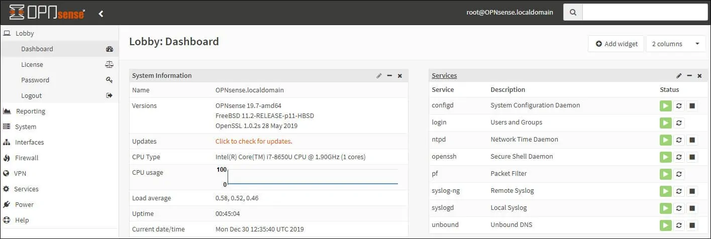
After a successful login, you will be sent to the OPNSense Dashboard.
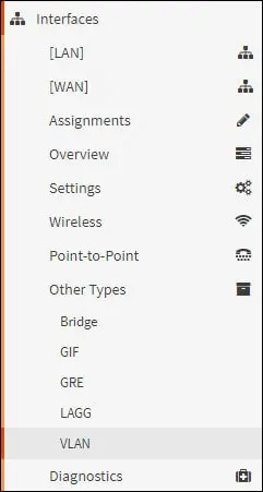
Access the Opnsense Interfaces menu, access the Other types sub-menu and select the Vlan option.
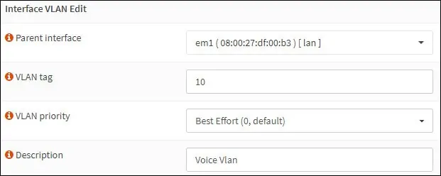
Access the VLAN screen, click on the Add button and perform the following configurations:
• Parent Interfaces - Select the Physical interface
• VLAN Tag - Enter the VLAN identification number
• Description - Optionally enter a description
Click on the Save button to create the Opnsense Vlan.
Access the Opnsense Interfaces menu and select the Assigments option.
On the Interface Assignments screen, select the new Vlan interface and click on the Add button.
Click on the Save button.
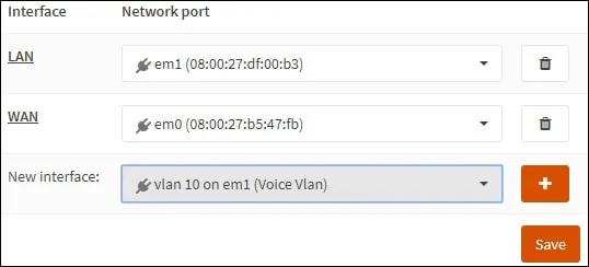
In our example, The Vlan 10 was assigned to our OPNsense firewall using the name OPT1.
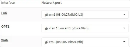
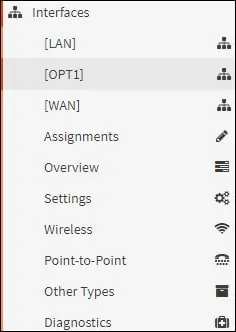
Access the Opnsense Interfaces menu and select the new interface.
In our example, we selected the OPT1 interface.
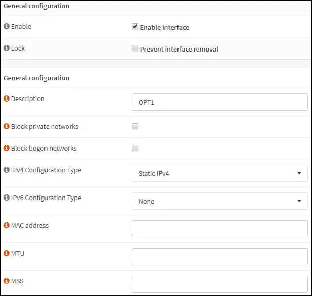
On the General Configuration area, perform the following configuration:
• Enable - Yes
• Description - Optionally, you may change the name of the Vlan interface
• IPv4 Configuration Type - Static IPV4
• IPv6 Configuration Type - None
• Speed and Duplex - Default
On the Static IPv4 Configuration area, perform the following configuration:
• IPv4 Address - Configure the Vlan interface IP address and netmask
Click on the Save button.
Click on the Apply changes button.

Congratulations! You have finished the Opnsense Vlan configuration.
Keep in mind that you need to create firewall rules to allow the new VLAN interface to communicate.
Tutorial - VLAN Configuration on Cisco Switch
Now, you need to perform the Vlan trunk configuration on the Network Switch.
In our example, we are going to show how to perform the Vlan configuration on a Cisco Catalyst Switch model 2960.
On the prompt screen, enter the administrative login information.
Use the configure terminal command to enter the configuration mode.
Create a new vlan, select an identification number and add a brief description.
Access the interface configuration mode and set the Switch port as a trunk.
Add the list of authorized Vlans to use this trunk.
In our example, the Switch port 40 was configured as a trunk.
The following Vlans were allowed to use this port as a trunk: 1 and 10.
Vlan 1 is the default native VLAN of Cisco Switches.
Don’t forget to save your Switch trunk configuration
Connect the opnsense LAN interface to the Cisco Switch port number 40.
Traffic comming from the Opnsense LAN interface will not have VLAN tag and will be a member of the Cisco Switch native VLAN 1.
Traffic comming from the Opnsense OPT1 interface will have the VLAN tag 10 and will be a member of the Cisco Switch VLAN 10.
