Would you like to learn how to perform the HP Switch Intervlan routing configuration using the web interface instead of using the command-line? In this tutorial, we are going to show you all the steps required to configure the VLAN routing feature using an HP Switch 5500 using the web interface.
Copyright © 2018-2021 by Techexpert.tips.
All rights reserved. No part of this publication may be reproduced, distributed, or transmitted in any form or by any means without the prior written permission of the publisher.
Equipment list
Here you can find the list of equipment used to create this tutorial.
This link will also show the software list used to create this tutorial.
HP Switch Book
Despite having a good knowledge related to computer networks and even have some certifications on the subject, Luke, a 26-year-old IT analyst has just received a mission to deploy a new network using only HP switches.
Follow Luke’s history and a step by step approach to a network project implementation created by a certified project management professional.
HP Switch Playlist:
On this page, we offer quick access to a list of videos related to HP Switch.
Don't forget to subscribe to our youtube channel named FKIT.
HP Switch Related Tutorial:
On this page, we offer quick access to a list of tutorials related to HP Switch.
Tutorial HP Switch - InterVlan Routing Configuration using the CLI
First, you need to create a voice VLAN.
A voice VLAN is a VLAN that will be used only for voice traffic.
Open a browser software, enter the IP address of your Switch and access the HP Switch web interface.

On the prompt screen, enter the administrative login information.
Factory default access information:
• Username: admin
• Password: (no password)
After a successful login, the administrative menu will be displayed.
Access the Network menu, and select the VLAN interface option.

On the VLAN interface screen, select the Create tab on the top of the screen.
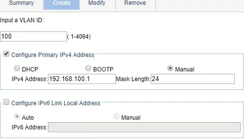
To create a new virtual interface, you will need to perform the following configuration:
• Enter the first VLAN identification
• Select the Configure Primary IPv4 Address checkbox
• Select the Manual option.
• Enter the desired IP address
• Enter the desired network mask
• Click on the Apply button

In our example, the following virtual interface was created: Vlan-interface100.
The Vlan-interface100 interface is using the IP address 192.168.100.1.
Every computer on the 192.168.100.0/24 network should point to 192.168.100.1 as the default gateway.
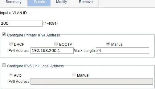
Create a second interface named Vlan-interface200.
The Vlan-interface200 is using the IP address 192.168.200.1.
Every computer on the 192.168.200.0/24 network should point to 192.168.200.1 as the default gateway.

The Layer 3 switch will be responsible for routing the packets between 192.168.100.0/24 and the 192.168.200.0/24 networks.
If you need to create a default route, access the Network menu and select the IPV4 Routing option.
On the IPV4 routing screen, select the Create tab on the top of the screen.
• Enter the network address
• Enter the network mask
• Enter the IP address of the network gateway

Don't forget to save your configuration.
Congratulations! You have successfully configured the Inter VLAN routing feature.

